

An automotive parts carrier approaches a transfer station at a slight angle. A laser aimed at the near corner can report the expected distance while the far corner is still out of position. If the station needs to know the gap at one specified face, that single reading may be enough. If the station needs to distinguish a square arrival from a skewed one, its measurement has to see enough of the carrier to make that distinction.
Measure one gap when one gap answers the question
A repeatable face on a carrier gives a fixed laser a useful reference. Draw the beam and show the worst expected arrival angle. If the spot stays on the target face, a distance band can support a simple process check. If a corner or cutout can move through the beam, the spot may end up on the background. Move the target or change the measurement layout before deciding where to set the band.
The DDK-F laser distance sensor specifications describe a point measurement and list the available ranges and signal options. Use the target distances from the station drawing when selecting the model. If the system needs to estimate both angle and distance, two suitable point measurements may be sufficient when both can see known faces. Keep their positions and the calculation in the station documentation.
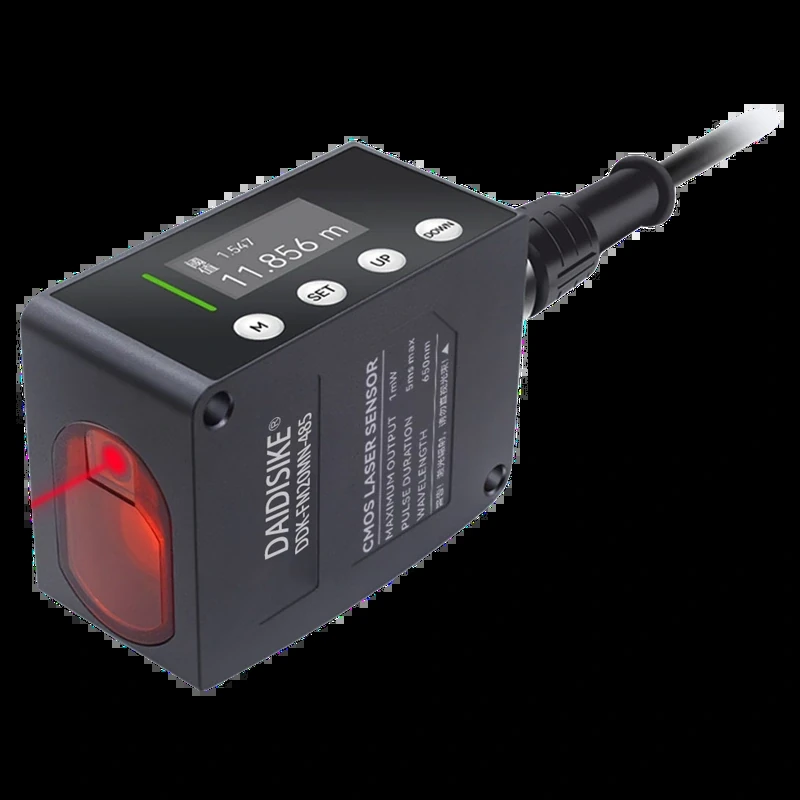
DAIDISIKE DDK-F laser distance sensor with display and cabled connection
Choose a scan plane when the shape matters
The DLD-50D Ethernet scan data specifications describe a two dimensional scanner that supplies measurement data over Ethernet. At a height where the scan crosses a solid carrier face, the receiving software can use multiple returns to estimate its orientation. A scan through an open rack or across a floor gap may omit the feature the calculation needs. Set the scan height from a drawing and verify it with the actual carrier.
Include a machine frame, post or another carrier that could block the line of sight. A plane extends the area sampled, but a hidden far corner can still be hidden. Check the scanner’s usable angular sector in the intended mount, the actual finish of the target and which returns the software needs when a carrier approaches at an angle.
Compare the information the controller must use
Test square, skewed and partially blocked arrivals. Write down the variable the station will use in each case: gap at a face, distance difference between two points, or a line fitted to scan returns. Give the controls team a rule for insufficient data before it writes a pass condition. Keep the checks within process measurement. Personnel protection requires its own equipment and validation.
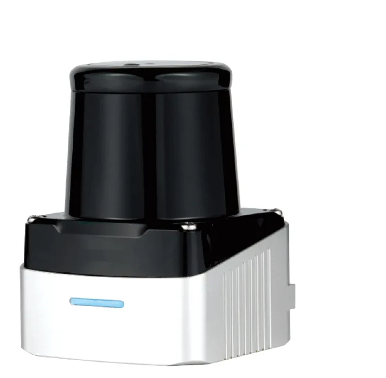
DLD-50D two-dimensional navigation and mapping scanner